1/72 Conversion Of the Hat WWI French 75mm M1897 into the Schneider-Canet 75mm PD06 or PD06bis commercial sale model.
Dated: January 11, 2010.
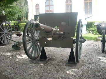
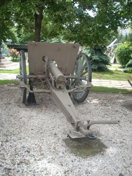
The Schneider-Canet 75mm's were only rivalled in popularity by Krupp's commercial 75mm versions. The following countries used Schneider-Canet 75mm's: Serbia, Bulgaria, Turkey, Romania, Portugal, Spain, Brazil, Mexico, Argentina & others all prior to WWI. There are 2 principal versions of this commercial product - the M03 or M04 & the PD06 & PD06bis. The principle difference between the 2 pairs is the positioning height of the barrel & the lower edge of the gun shield. I have included some photos to show these differences. I have chosen the PD06 & PD06bis as these were used by Serbia in WWI & I am working on a 1914/15 Serbian force. From a wargames perspective these two designations are visually identical. Attached are front & rear views of a surviving example from the Bucharest Military Museum .
Stage 1 - the Hat Model - areas to remove.
The areas painted white need to be cut off & removed.
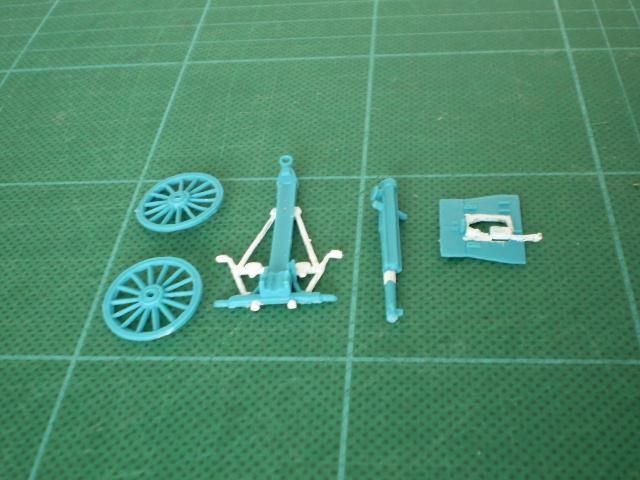
1. Remove all the assembly for the crew seats, wheel breaks etc as those for the commercial version are very different.
2. Remove approx 3mm (max 4.5mm) from the Gun Tube & Recoil System piece just in front of the slide base. The barrels of the 1906 version were 3 to 4 calibres shorter than the M1897, BUT still had the forward lugs to lock the barrel to the slide in its long recoil.
3. The shape of the Gun Shield aperture is very different & the indirect site is behind the shield (largely invisible). With the changes to be made to it is easier to cut out the marked shield sections & back fill. This should give a rectangular opening basically 8mm high & just under 7mm wide.
4. Remove the 2 lugs to receive the gun shield as this will have to be repositioned.
Stage 2 - partly completed conversion.
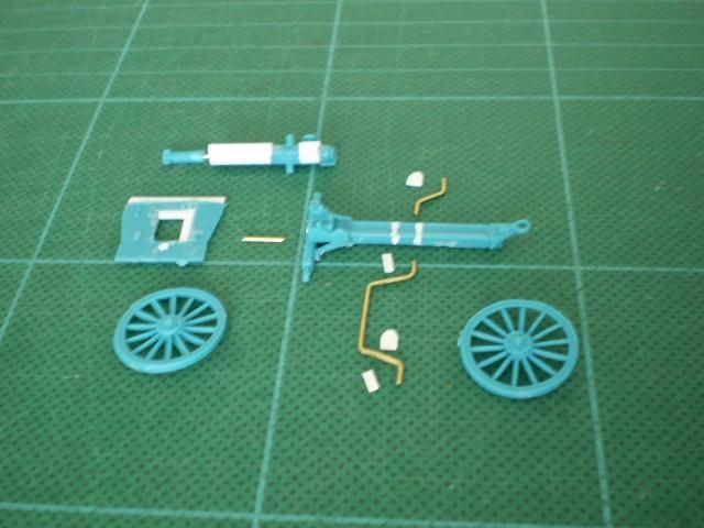
1. The Gun Shield.
A. Here the modified aperture has been part filled by 2 short sections of 1.5mm strip. I have done the vertical 1st using an 8mm length, then the horizontal with a 5mm length.
B. As the aperture has a concave top I used Tamyia Basic Plastic Putty. Smear in a small amount wait a few minutes for its outer surface to start to dry (as this stuff is otherwise @#$% tacky & impossible to shape). Then carefully press into the desired curve (see next photos).
C. The height of the Gun Shield is raised by adding a strip (19mm long) of 1.5mm strip to the top of the original.
D. The white dot under the aperture is where the shield needs to be drilled to pin to the carriage / trail. The corresponding point on the trail piece is in the centre of & slightly up from the line of the original lugs. This slightly raises the shield (& is why in stage 1 the aperture is cut down to the top of the lower shield section).
2. The Gun Tube & Recoil System
A. Here the short front section has been pinned, but not closed & glued to the main part of the Gun Tube & Recoil System.
B. The long white area on the main Gun Tube & Recoil System piece is made of 3 pieces of 1.5mm U channel glued to the triangular underside of the recoil slide to make it square in section. The best method is 1st glue a piece U side inwards on to the apex of the original pieces underside. Then placing then U side inwards glue the 2 other pieces to the left & right sides.
C. Then there is a 5mm to 6mm gap to allow the converted barrel to still fit into the carriage trunnion slots (this area has a raised section in it that would otherwise need to be cur out).
D. Finally there is the short white section of 3 pieces of 3 pieces 4mm long 1.5mm U channel. This is just like B but is snug in against the breech underside.
3. The Gun Carriage / Trail etc.
A. The 2 white lines on the trail mark where the 2 brass rods will be put into drilled holes for the wheel brakes & crew seats. The forward line must be drilled through completely as this is for the wheel brakes & the Gun Layers seat (on the left) - the Long Brass Rod. The 2nd line is drilled from the right & is 4mm to 5mm back from the first & is the support for the Breech mans seat (the Short Brass Rod).
B. Fit the long rod through the hole in the trail & check its alignment with the wheels before doing C & D below.
C. The 2 straight white pieces are for the wheels brakes & are of 1.2mm Half-Round & are 4mm long. These glue to the short outer ends of the long brass rod (which are 4mm long) - the curved side glues to the rod the slightly concave inner side will face the wheels.
D. The 2 small pieces with 1 curved end are the gunners' seats & are 4 or 5mm long & 3or 4mm wide (they are cut from plastic card). The Gun Layers seat glues at the left end of the central section (before it bends up) of the longer rod & faces forward. The Breech Man's seat faces towards the trail (90 degrees to the line of the Gun Layers seat) & glues on the top 'flat' section of the short brass rod.
4. Making the Rod Sections
A. For the Long Rod - cut a 40mm (or a couple of mm longer) length of 0.7mm Brass Rod. Mark the centre, then mark 8mm left & right of the centre. Bend on these 8mm marks the outer sections up in a 45 degree angel (both in the same direction). From the base of each 45 degree bend mark 8mm out along the angle forward & mark, then bend the final 4 or 5mm (approx) back so it is parallel with the main central section. The outer ends may need trimming when the rod is inserted in its hole so they align well with the wheels.
B. For the Short Rod - cut a 15mm (or slightly less) length of 0.7mm Brass Rod. Mark 4mm in from 1 end & bend at 45 degrees, then mark 6mm along this line & bend back so the two end sections are parallel. The final end past the 2nd bend should be approx 4mm also.
Stage 3 - Completed Rear View
Here the positioning of the rods & their attachments can be seen.
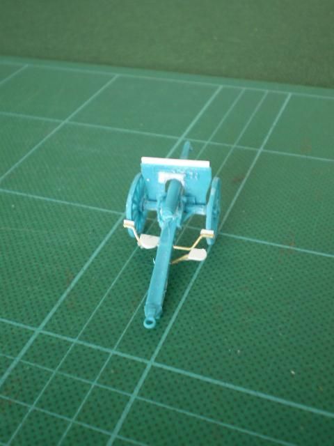
I use the Seated Crew Figures designed to ride the limber as Gun Layer (on the left - facing forward) & Breech Man (on the right - facing across the trail). Remember these guns are long recoil so it is correct for the Breech man to be well back from the loaded position of the breech.
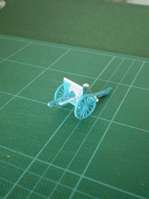
Stage 4 - Completed Front View
Here the use of the Plastic Putty to create the top arch on the gun shield aperture can be clearly seen.
Finally - Additional Photos of actual artillery pieces.
The two photos of the 75Mle07 from Bucharest show the front & rear views of a PD06 & show the distinctive features I have tried to recreate in this conversion.
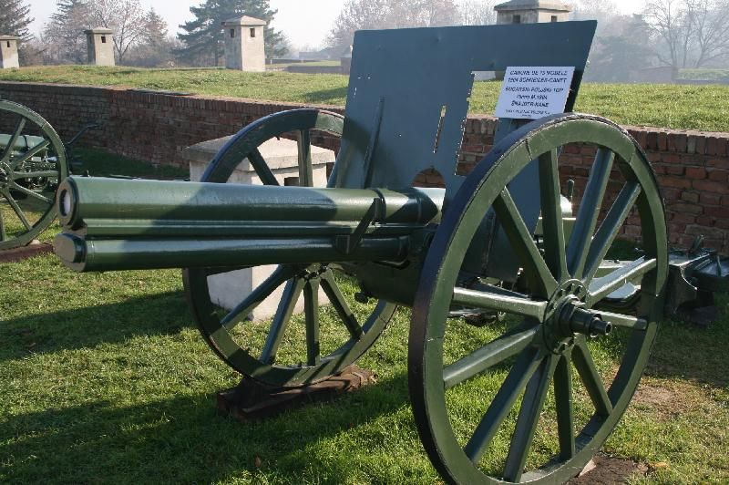
The Photos of the Portuguese & Bulgarian Guns show two different versions of the M03 or M04. Note the significantly lower position of the barrel in both.
Bulgarian
Portugese
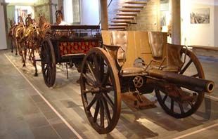
The trunnions pivot barely above the line of the axel tree. Too replicate this barrel position the Trunnion Slot section on the M1897 carriage / trail & its raised inner section would need to be cut out & probably the gun tube & recoil system pinned in place.
Further on the M03/04 note the lack of the lower gun shield segment - this would need to be detached in part (only in part to ensure a surface to pin the shield to the carriage).
The difference between the 2 M03/04 pieces is in the recuperator & barrel slide sections. The Bulgarian gun has a narrow smallish square full length recuperator & slide, to replicate this, the following changes should be made the M1897 barrel piece:
1. Shave approx 1mm off the bottom triangular part.
2. Shave back to two side ribs down the side of the slide / recuperator so they are level with the barrel max width.
3. Square off the recuperator / barrel slide with a full length section of 2.4mm U channel (flat side out).
4. Replace the front section of the barrel (the final thinner bit ending in the recoil lugs) with a piece of 2.5mm Rod so the barrel is of equal thickness. The barrel must be 5mm shorter than the original M1897 Barrel.
The Portuguese gun's barrel is the same basic form as the PD06.
The Portuguese gun Photo is the one Armand posted before Christmas, the Bulgarian Gun is from the Belgrade Military Museum .
Brennan Tate
New Zealand
Many thanks to Mr. Tate.