1/72 Building a British 2.75inch Mountain Gun for WWI
Dated: January 01, 2010.
Attached are a series of photos of a conversion / scratch build I have done that should fit well with Hat's series of WWI Figures.
The 2.75" Mountain Gun was the mainstay of British, Indian & Dominion Mountain Batteries during WWI seeing limited service on the Western Front but wide service in Salonika (the Balkans), Gallipoli, Palestine, Western Desert, Mesopotamia, West Africa (& East Africa?).
Stage 1 - is the Carriage Pieces.

Carriage main parts are :
1. Wheels from Airfix French Napoleonic artillery piece
2. Carriage from the Airfix British Napoleonic artillery piece
3. The Limber Trail from Airfix French Napoleonic artillery piece
The areas painted Blue need to be removed.
Stage 2 - is the 2,75inch converted carriage plus pieces for gun shield & pieces to act as barrel receiver
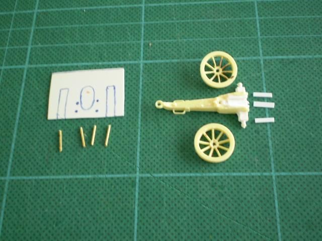
1. Looking at the carriage the sections in white show the inserted segment from the Limber Trail from Airfix French Napoleonic artillery piece. I usually put a pin in the section of Limber Trail that would slot into recessed slot visible in the original Carriage from the Airfix British Napoleonic artillery piece. Then glue things in place. Using the pin adds extra strength.
2. Just in front are the 3 short sections of strip to be fitted in to the recess between the trunnion mounts on the carriage. These will give a good snug fit to the recuperator section of the new gun.
3. Also visible is he gun shield marked up. For the oval slot I drill a series of holes around the inside of the line. Then join the holes up with a scalpel. Finally filing out & evening up the oval. The marked oval should be 11mm high & 6mm max width. When filed out it needs to be 7 or 7.5 mm max width & 12 or 13mm high. The wheel slots are just cut snips & scalpel.
4. The 4 pins enable the gun shield to fit securely over the axel tree and stay in place. I did this because I like the gun as much without shield as with.
Stage 3 - is the 2,75 inch gun tube pieces & a completed tube
These are the gun tube parts & a completed assembly. From the top left:
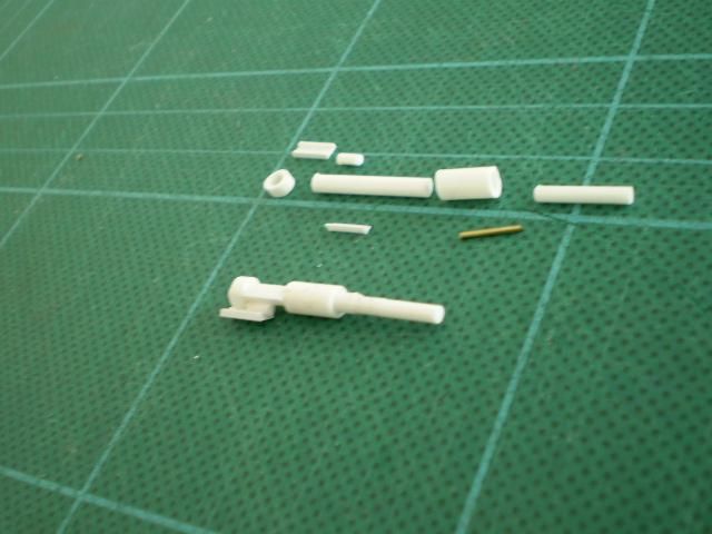
1. A 7mm section of 2.4mm u section strip.
2. A 3mm section of 1.5mm rod.
These form part of the breach assembly & are added last.
3. A 3mm section of 4mm tube - this is the breech block.
4. A 17 or 18mm section of 2.5mm rod - this is the rear section of the gun tube.
5. A 6mm section of 4mm tube - this is the barrel join bulge as the 2.75" is a screw gun (2 part barrel). This piece fits over the 2.5mm rod so that approx 2 or 3mm of the rod projects from the front end.
6. A 10mm section of 2mm rod - the front section of the barrel.
7. A 7 or 8mm section of 1.2mm v angle strip, this fits between the 2 sections of tube on the underside of the barrel to give a good fit to the recuperator section when assembling.
8. A 4 or 5mm 0.7mm brass rod pin (roughly my standard length) to join the two barrel sections securely.
Assembly order is normally:
A. Glue 3. to one end of 4. so there is a slight recess.
B. Glue 5. onto 4. so that 2 or 3mm of 4. projects out the other end (this is the end that does not have 3. attached)
C. Drill both 4. & 6. then fit the pin (8.) and glue. Take care so that 6 is centred when attached to 4.
D. Glue 7 snugly to the underside part of 4. between 3. & 5.
E. Glue 2. into the u of 1. so that half its length projects forward.
F. Glue the assembly in E to the left hand side of the barrel assembly so that it is vertical & the U section strip projects 2mm at least back behind the breech piece, To do this
best the short section of rod fits snugly into the intersection of the V angle, the Breech section & the Main gun tube.
Stage 4 - is the 2,75 inch recoil system pieces & completed system
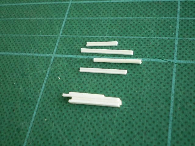
Parts from the top:
1. A 14mm section of 1.6mm u channel.
2. A 21mm section of 1.6mm u channel.
3. A 17mm section of 1.5mm rod.
4. A 17mm section of 1.6mm u channel.
Assembly:
A. Glue 3. into the u channels of 2. & 4. so that approx 1mm (max) extends in front of the two sections of channel. The two sections of channel must be even with each other at this projecting end (this is now the front of the recuperator system).
B. Glue the flat side of 1. to the flat side of 2. so that it is 2 or 3 mm forward of 2.'s rear end. This gives space for the breech section of the barrel to fit into.
Stage 5 - is the 2,75inch completed components carriage shield gun tube recoil system
Looking at the carriage the sections in white show the inserted segment from the Limber Trail from Airfix French Napoleonic artillery piece. Also you can see the 3 short sections of strip added in between the trunnion mounts to give a good snug fit to the recuperator section of the new gun.
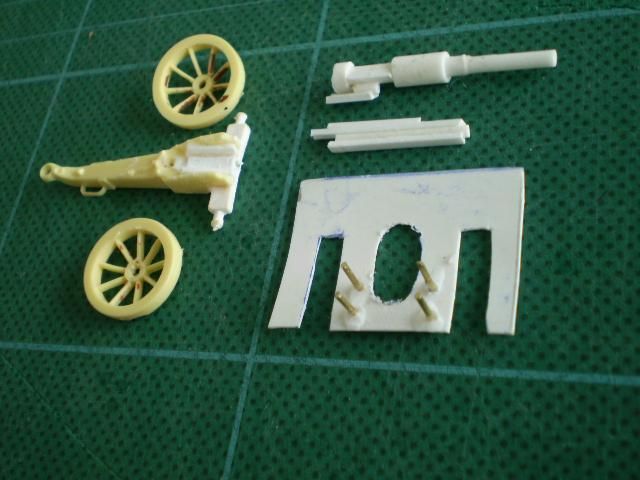
Stage 6 - is the 2,75inch side view of assembly with near side wheel removed
This is a side view of the completed Barrel & recuperator sections fitted onto the carriage.
This shows the way the barrel section fits onto / into the top U channel section of the recuperator system from back of breech to almost the front of the barrel join piece.
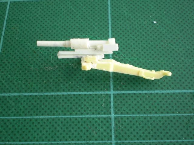
Stage 7 - is the 2,75inch completed but shield not fitted
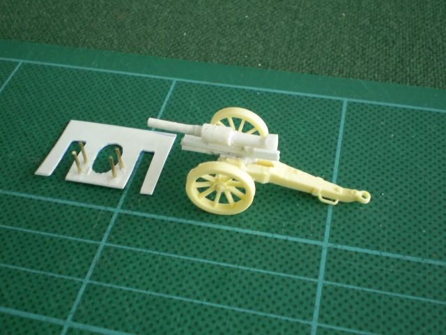
Stages 8 & 9 are views of the completed piece - front & rear.
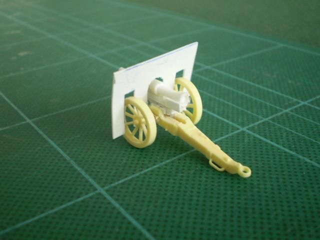
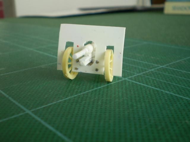
As I had only photos & illustrations with very few dimensions it is likely that the model is slightly over scale, however it looks good with 1/72 scale figures giving a look very like the photos. As with all such models the barrel pieces ARE over scale to make them robust and to look right. The front section of the 2.75" mountain gun's barrel is at most 3.75" in diameter, this is would be 1.33mm in strict scale. The result would be both fragile & just look wrong as it would be little bigger than many rifles! I hope the above is helpful & clear. All comments, improvements etc are welcome.
Thanks,
Brennan Tate
New Zealand
Many thanks to Mr. Tate.